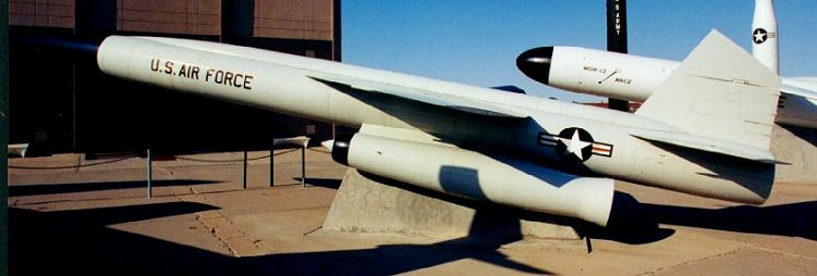
Bomarc Missile at Kirtland AFB Museum
The idealized ramjet is both descriptive and oversimplified. The basic construction can be almost as simple as that shown, as seen in the early Bomarc engines developed in the 1950's.
The Bomarc was rail launched and propelled by a rocket to about Mach 2 before ramjet takeover. It was designed to cruise at Mach 2.8, from sea level to 100,000 ft, and had a range of 440 miles (CIM-10B). Each ramjet engine (Marquardt RJ-43-MA-7) produced 12,000 lbf thrust.
Note in the figure the inlet diffuser, the widened body where the combustion chamber is, the narrowed exhaust nozzle throat, and the flared exhaust nozzle. Note also that the the body is almost entirely made of three conical shapes made from rolled sheet steel. These are parts of but one possible design.
Bomarc Missile at Kirtland AFB Museum
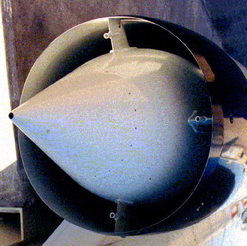
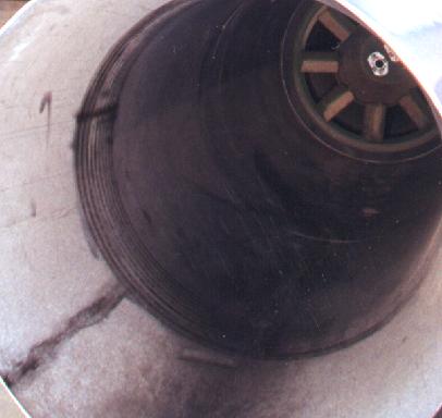
Bomarc RJ-43-MA-7 Inlet
This supersonic diffuser is smoothly curved to allow the air to flow around it with very little drag. The inlet lip is canted inward to match the flowlines of the air going around and through the inlet. There are four vanes used to hold the diffuser in place. The hole in the nose of the diffuser is used to capture high pressure air to spin the fuel pump. The pitot tubes in the inlet vanes are probably part of the fuel control system.
The combustion chamber on the Bomarc included the fuel injector, flame holder, and igniter. Other than these it was an empty tube. By current ramjet standards it was quite long, allowing considerable time for the fuel to mix and completely burn. The structural shape of the combustion chamber is made of sheet metal formed into truncated conical shapes then welded together.
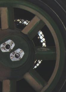
Flow Straightener
In this figure you can just see the grid-type flow straightener. This was used to help smooth and control the air flow, especially at high angles of attack. The Bomarc was a surface-to-air missile intended to attack aircraft which were trying to maneuver to escape.
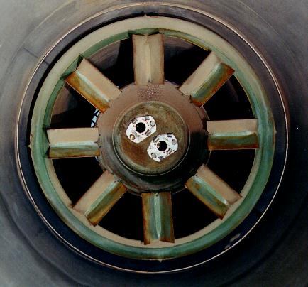
Bomarc CIM-10A Flame Holder
The flame holder is a gutter-type with both radial and axial gutters to ensure efficient combustion. The fuel injectors, from what I could gather, were Spray Bars just upstream of the flame holders (hidden by the flame holder). The CIM10-B used a can-type flame holder because it was better able to maintain the flame at the higher (Mach 2.8 vs 2.5) flight speed.
This engine used two flares to ensure fuel ignition. The flare holders can be seen in the center of the flame holder.
Bomarc CIM-10A Combustion Chamber
This image shows the hollowness of the combustion chamber behind the flame holder.
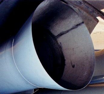
Bomarc Exhaust Nozzle
The Bomarc exhaust nozzle is formed by the intersection of two conical sections made of sheet metal sized to create a throat. On close inspection there is a short transition section at the throat to eliminate the, otherwise, sharp edge. I've heard that operational missiles had an ablative coating in the nozzle, though this has not been confirmed. There were probably some drag losses from the shape and heat losses from the metal in contact with the air. These may have been tradeoffs to cool the metal which, on the inside, was subjected to the 2,500-3,000 degrees f exhaust.
| Return to Top of Page |
Updated: February 22, 2001