FOREWARD
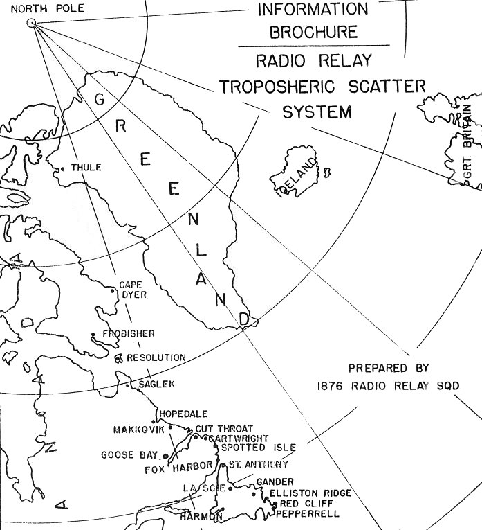
This brochure was prepared by the 1876th Radio Relay Squadron, to provide a general over-all picture of the Pole Vault Tropospheric Scatter System to interested personnel. The cover page shows a
diagram of locations which made use of the Pole Vault System.
CHAPTER 1
INTRODUCTION
Tropospheric Scatter System
The remote radar defense systems in this area are vital to the defense of North America. The mission of the 1876th Radio Relay Squadron is to provide communications to support these systems.
Until 1955 when the Pole Vault Tropospheric Scatter System was put into operation, point-to-point communications in this area constituted a serious problem. Frequent ionospheric storms disrupted the flow of information from isolated radar stations to air defense centers. The answer to the problem seemed to be installation of a line-of-sight microwave relay system. Installation and manning costs would be high for the more than fifty stations required to provide adequate coverage for the radar systems.
During the past years various research agencies have sought a means of overcoming the line-of-sight limitation. Two of these agencies were Bell Telephone Laboratories and Lincoln Laboratories, which at the request of the United States Air Force approached the problem with the definitive aim of improving arctic communications. After a period of intensive research engineering, they proposed a solution utilizing a combination of known facts about tropospheric propagation and recent developments in vacuum tubes and radio circuitry.
With the support of the Northeast Air Command (no longer in existence), a test circuit was installed in Newfoundland in late 1953 to evaluate the proposal. "Tropospheric Scatter" communications were established over a 150-mile path from St. Anthony to Gander without repeater stations, to determine the capability of this new means of overcoming the line-of-sight characteristics of UHF. Emissions of approximately 500 megacycles at 500 watts and 4,000 megacycles at 10 watts were used in this test. Best results were obtained with the lower frequency, although the 4,000 megacycles signal was also readable. Even before the test was completed, such satisfactory results were obtained that it was decided to go ahead with a complete installation of this new equipment, and to eliminate the previously-planned conventional microwave system. This substitution resulted in an immediate savings to the Air Force of many millions of dollars. The possibility exists of realizing much greater savings in the future by utilizing tropospheric scatter equipment in other areas of our world-wide defense network. However, the most important fact is that we now have a reliable communications system which is immune to frequent ionospheric disturbances. To insure that the installed system would perform properly, it was designed and engineered to standards well above the requirements actually indicated by the test.
The Radio Relay System can be compared with a long-distance telephone network like those operated by American Telephone and Telegraph Companies in the States and our own Newfoundland Long Lines System. The transmitters, receivers and antennae at each station simply replace the Long Cable that would otherwise be necessary. Each station forms an integral part of the over-all Pole Vault system. The Radio Relay Squadron was organized December 1954 in order that the Radio Relay System could be operated as a complete network regardless of the user of an individual circuit.
Where terrain is such that large radar installations can’t quite cover the approach routes, small radars fill in the gaps. Appropriately, they are called Gap Fillers. The radar fence in this area uses them. Communication between the Gap Fillers and parent sites is by AN/FRC-39 Tropospheric Scatter Systems and operated by the Radio Relay Squadron.
In outward appearance a tropospheric scatter installation resembles an overgrown microwave station. The dominant features of the installation are the antennas, which in the case of the Pole Vault installation are 60-foot parabolas. The antennas used on the Gap Filler installations (AN/FRC-39) are 28-foot parabolas. The Gap Filler installation is a smaller version of a Pole Vault installation having many newer features. A brief comparison of the two systems is as follows:
|
|
Gap Filler |
Pole Vault |
|
Frequency |
900 mcs |
650 mcs |
|
Distance between sites (approximate) |
60 miles |
180 miles |
|
Power transmitted |
1,000 watts |
10,000 watts |
|
Antenna size |
28 feet |
60 feet |
|
Klystron |
Air Cooled |
Liquid cooled |
|
RF input to Klystron |
10 watts |
25 watts |
|
Personnel |
5 |
15 |
The multiplex system is conventional frequency division type widely used for carrier telephone work. The receivers are relatively new in design, and use tubes developed in recent years in circuits which help overcome the extreme fade and noise conditions associated with tropospheric scatter. Frequency modulation is employed; consequently the over-all noise of the system is minimized.
The theory of tropospheric scatter propagation is not completely understood at the present time. It is thought that the transmitted wave is scattered to the earth by passing through successive particles with different refraction indices, which cause abrupt changes in the direction of the wave at each boundary surface. Scatter takes place at altitudes under twenty thousand feet.
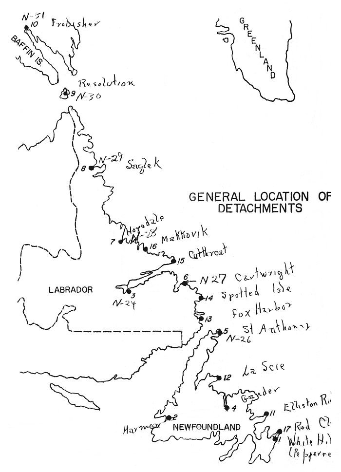
Diagram showing the locations of the Pinetree Line Long Range radar stations and the Gap Filler stations in Newfoundland and Labrador.
Scatter radio systems represent the major innovation in military communications since the advent of "conventional" microwave relay. It is possible to visualize all the future military and commercial applications of this development, but it is safe to predict that its impact on the communications field will be well marked.
CHAPTER 2
Organization Synopsis - 1876th Radio Relay Squadron
- Manning of the 1876th Radio Relay Squadron:
- The attached
diagram illustrates the organization of the 1876th Radio Relay Squadron. The Radio Relay System provides communications over a total distance of 1,800 miles. The squadron is required to man ten sites and seven gap fillers along this route. The southern terminal is designated a control station for the Northern stations. Most of the stations are attached to neighbouring AC&W Squadrons for quarters, rations, and most administration. The remaining stations are supported directly by the Squadron Headquarters. The list below outlines the authorization for a typical station.
The manning of these stations at present is augmented by Contract Technicians of the Bell Telephone Company of Canada. Four (4) Bell representatives are utilized at the Squadron Headquarters for system engineering, training, and maintenance supervision assistance. The remainder are assigned to the various sites throughout the system.
Manning authorization of the 1876th Radio Relay Squadron for two typical stations is listed below:
TERMINAL STATION
|
No. Auth. |
Job Title |
AFSC |
|
4 |
Radio Relay Equipment Repairman (Carrier) |
30450B |
|
4 |
Ground Communications Equipment Repairman (H) |
30453 |
|
4 |
Radio Relay Equipment Maintenance Technician |
30470 |
|
4 |
Ground Communications Equipment Technician (H) |
30473 |
RELAY STATION
|
No. Auth. |
Job Title |
AFSC |
|
3 |
Radio Relay Equipment Repairman (Carrier) |
30450B |
|
5 |
Ground Communications Equipment Repairman (H) |
30453 |
|
1 |
Radio Relay Equipment Maintenance Technician |
30470 |
|
1 |
Ground Communications Equipment Technician (H) |
30473 |
In addition to the above, 304X1, flight facilities repair personnel, are authorized for the sites where this organization is charged with maintenance of NAVAIDS.
- Operations:
- The Operations Officer is charged with the responsibility of supervising the training and circuit analysis section which are discussed at some detail in later paragraphs. In addition, he is responsible for the proper operation of the Pole Vault, Dew Drop, Gap Filler, and NAVAIDS system. This includes supervision of control station activities and the issue of operational directives to insure their proper operation for maximum in-service time of all circuits. Circuit orders and circuit engineering are controlled by the operations section.
- Coordination with and supervision of Detachment Commanders and coordination with other Squadron agencies are functions of the Operations Officer. He is also authorized to coordinate and communicate directly with North Atlantic AACS Region to accomplish Squadron mission.
- Training:
- Newly assigned personnel are given a one week indoctrination course at Station Headquarters. This course is designed to acquaint airmen with their duty position at the station they will be assigned in their particular AFSC. The equipment used is unique in the Air Force. Radio Engineering Laboratory receivers, transmitters, and Klystron amplifiers make up the major components of the radio equipment. GCE type 51 British, 36 channel carrier equipment is used. The power source is 100 kw Cummings Diesel generators.
- It takes three to four weeks from the date of assignment until the airman arrives at his duty station. This includes the processing, training, and delays encountered in traffic due to weather which could delay his departure from Pepperrell Air Force Base. Further delays may be encountered at Goose Air Base where all personnel being assigned to the northern stations must be processed. This results in additional time loss in the replacement of personnel. The above problems coupled with the fact that the average individual requires from one to two months "on the job" training at the detachment results in a time lapse of possibly three months before the airman can assume his duties in an efficient and capable manner.
- The majority of personnel assigned have recently completed the training course pertaining to their AFSC, and are at the three level. This has increased the training problem greatly since these airmen have had no practical experience and only the theoretical training at Training Command Schools and the Squadron Training Course.
- Circuit Analysis
- The system is capable of furnishing 36 voice frequency channels from 200 cps to 3400 cps. Each of these voice channels could contain 24 teletype circuits, on the "tone-on, tone-off" type or 12 frequency modulated teletype circuits. A three circuit order wire of 300 cps to 2800 cps is furnished for Radio Relay Squadron maintenance communication between stations. Communications service is made available for SAC, AACS, AC&W, Canadian Department of Transport, RCAF and US Navy.
- Circuit outages reports are analyzed to determine not only the efficiency of the system but also to discover deficiencies in equipment and personnel. The data gathered by the analysis section is used to isolate recurring component breakdowns, which may call for additional technical engineering. Other studies of this information may reveal areas where personnel are not qualified and additional training is required. Records are maintained of circuit time loss due to poor propagation. These records are useful in determining if one radio path is better than another, or if paths between different relays are better than others. Studies are made of each separate circuit, individual system between stations, and by individual stations.
- A full duplex teletype circuit shown as being out north (or south) for 30 minutes would have a total recorded outage time of 15 minutes. This is halved because it is still usable in the other direction. In the case of an odd number, the odd half minute is recorded as one minute of outage. Example: A full duplex circuit out in one direction for 13 minutes would have a total recorded outage of 7 minutes. The same circuit out in both directions would have a total recorded outage time of 13 minutes.
- The outage time for a half duplex teletype circuit is not halved and is charged with the full time as shown on the Outage Summary.
- A voice circuit is not considered usable at all if it is out in one direction, so outage time for these are not halved and is recorded as shown on the Outage Summary.
- In the case of a System Outage (all circuits out in one direction between two detachments) the time duration of the outage is recorded against each circuit effected with the same considerations as previously outlined.
- An attempt is made to account for all outages for all reasons and these outages can usually be charged against one of the following major components (or reasons), and these are used during initial recordings as a basis for further analysis.
|
1 |
Basic Transmitter |
|
2 |
Klystron Amplifier |
|
3 |
Antenna & Feeder System (both send and receive) |
|
4 |
Receiving Equipment |
|
5 |
Teletype Equipment (detachment only) |
|
6 |
Power Failure (diesel source) |
|
7 |
Poor Propagation |
|
8 |
Using Agency |
|
9 |
Heat Exchanger |
|
10 |
Plant Error |
|
11 |
Held out for Test |
|
12 |
Equipment Changeover |
|
13 |
Unknown |
|
14 |
Carrier |
|
15 |
Irregularities |
|
16 |
Teletype Relays (No longer analyzed due to improved equipment) |
|
17 |
Noisy |
|
18 |
Cleared before located |
|
19 |
Tie line power |
|
20 |
Diversity equipment |
|
21 |
Patching to clear trouble |
|
22 |
Inter-connecting agency |
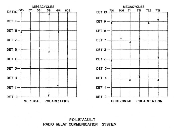
Diagram showing Pole Vault Radio Relay Communication System Frequency Plan.
Irregularities (See #15) above is a term used by this section under which outage time is accounted for that could not be justly charged against operational equipment but holds some significance from the standpoint of engineering. Outages recorded under this heading would indicate damage by weather, klystron off due to dynamite blast in area, etc.
A detailed analysis is accomplished on:
|
1 |
All voice circuits when the monthly operational time is less than 95% |
|
2 |
All teletype circuits when the monthly operational time is less than 90% |
|
3 |
All systems when the time lost exceeds 5 hours |
|
4 |
All component failures when circuit outage caused by a specific component exceeds 50 hours |
- Outage Time Recording Methods:
- Normally all outages for circuits south of Det #3 are reported by Det #1 and all outages north of Det #3 are reported by Det #3. Detatchment Locations The Daily Outage Summaries as forwarded by these detachments are the sole source of information for compilation of data.
- Maintenance:
- The Maintenance Section has the function of correcting equipment deficiencies, engineering modifications, formulating maintenance procedures, and monitoring alignment of the system. The Maintenance Section uses the data of the analysis section to determine in which equipment component failures occur. Methods of correcting these conditions are sought through research of similar difficulties and solutions thereto. When difficult maintenance situations occur at the outlying stations, teams of specialists from the Maintenance Section can be dispatched to direct or assist in the repair of the equipment concerned.
- Supply
- Technical supplies for the system are contracted for through the Marconi Company of Canada. The supply section at the Squadron Headquarters coordinates supply requirements directly with each station concerned.
- Housekeeping supplies for two stations are supplied from the Squadron Supply Section. The other stations receive this equipment from the unit supply of the AC&W Squadron to which they are attached.
CHAPTER 3
Technical Description (Pole Vault)
The data presented here is general in nature. Our intent is to provide interested personnel with a basic understanding of this system.
- Introduction:
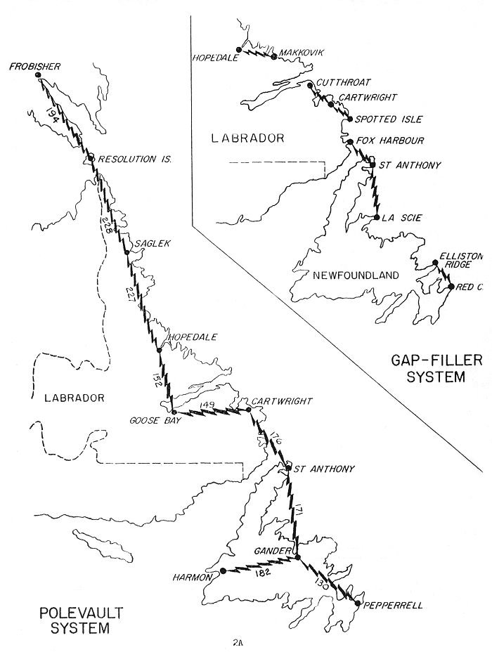
- The Radio Relay Communications System provides voice, teletype, and facsimile circuits between a total of 10 Pole Vault and 7 Gap Filler stations. These stations are in approximately the locations shown with distances along the routes between adjacent sites as indicated.
- The channel requirements in the Pole Vault system call for some channels going over the total length of the system, some channels over half the system, and some channels over only one section between adjacent stations. These requirements include additional reserves for further expansion. The basic channel capacity allows for a maximum of 36 voice channels plus a group of three channels which serve as engineering and order-wire channels. According to the channel requirements which decrease as the system progresses from Det 1, Det 2 towards Det 10, the channel capacity decreases from 36 to 24 and 18 as far as the provision of multiplex equipment is concerned. As mentioned above, a group of three channels is provided at each station for order-wire purposes. Apart from this utilization, the three channels represent an emergency group which are expected to remain in operation even after the main traffic channels are not usable due to excessive radio fading conditions.
- The requirements of the communications system as laid down in paragraphs 2a and 2b would conveniently be met by a UHF or microwave system with a number of repeater stations spaced at intervals of approximately 30 miles. This spacing cannot be increased appreciably because of the line-of-sight requirement. Costs of installation and complexity of maintenance are the main disadvantages of this type of system. Contrary to conventional systems, this Radio Relay System makes use of beyond-the-horizon propagation which allows a spacing between adjacent stations up to several hundreds of miles as shown on the locations diagram. It has been proven by extensive tests that the signal strength beyond the horizon at UHF frequencies is far above previously expected values, although, of course, a considerable drop of signal level as compared to "line-of-sight" conditions still has to be taken into account. To compensate for this drop, a considerable amount of transmitter power and very high gain antenna systems are necessary.
- According to the possibility as outlined in the preceding paragraph, the system employs the techniques of conventional UHF-FM-links, but without using the large number of repeater stations. The only difference as compared to conventional systems is the use of 10 KW transmitter power, very large parabolic antenna and the application of space diversity reception with two independent receiver antennas several hundred feet apart. Because of the generally low level of the received signal, the internal receiver noise is the most significant factor as far as the reliability of the transmission is concerned. Since this noise is proportional to the bandwidth, it is possible to increase the reliability by decreasing the bandwidth with a corresponding decrease of the maximum number of channels which can be transmitted. Practical use of this possibility is made by the provision of separate narrow band receiving amplifiers which allow for the reception of the group of three channels as outlined in paragraph 2.02. These amplifiers can manually be brought into operation when the wide band circuits become unusable because of extremely unfavorable propagation conditions. Similarly a medium band amplifier has been provided for and is expected to increase the reliability of transmission on those paths where not more than 12 channels are required. NOTE: During four years of operation we have not had poor enough conditions to require this feature.
- The equipment employed in the system utilizes techniques that have been standard practice for a number of years. The multiplex equipment manufactured by General Electric Company Ltd. Of England, the Voice Frequency Carrier Telegraph equipment, manufactured by Standard Telephones and Cables Ltd., and the 431A Voice Frequency Carrier Telegraph manufactures by Northern Electric Co. of Canada, are standard commercial equipments.
- The RF equipment, consisting of Basic Transmitter, page 28, Power Amplifier, page 29, and Receiver, page 28, were designed and manufactured by the Radio Engineering Laboratories of New York especially for this system.
- The 60 foot parabolic antennas manufactured by the DS Kennedy Company of Boston, and the RF Feeder system use transmission and radiation methods common to radar and microwave systems.
- Speech and teletype signals from the operations building are fed to the main distribution frame where all cross connections for speech or teletype circuits are made.
- Speech and teletype signals are fed to the multiplex and VFCT equipment where, through the use of frequency division, the various channels are placed on a baseband 300 cycles - 170 kilocycles wide. Three channel units, utilized for engineering or order-wire purposes are available at all stations and operate on the 300 cycle to 9500 cycle portion of the baseband. Multiplex unit with facilities for up to 36 traffic channels are available between stations, and operate in the 12 kilocycle - 160 kilocycle portion of the baseband.
- The baseband signal, containing the three engineering channels and up to 36 traffic channels, is used to phase-modulate the Basic Transmitter. This transmitter with an output of 30-40 watts, drives the klystron power amplifier to an output of at least 10,000 watts.
- The RF energy from the power amplifier is fed through 3 1/8 inch coaxial line to a coax RF patch bay that enables patching either the main transmitter or standby transmitter to the antenna or to the dummy load as required. A short distance from the coax RF patch bay is a coaxial-to-waveguide transition. Waveguide 7.5" x 15" is used to transfer the RF energy to the antenna. The waveguide is ended in a horn with inside dimension 15" x 15". The use of the horn provides optimum electrical match between the impedance of the waveguide and that of the air, a nearly optimum primary antenna radiation pattern, and a better means of receiving the incoming signal from the distant station. Since this incoming signal has a polarization in a plane at 90 degrees to that of the transmittal signal, a flat ridge type of transition placed in the horn is able to receive the incoming signal without interfering with the outgoing transmitted energy.
- The antennas are 60 foot diameter parabolas made up of aluminum screen sections punched and stretched to form a reflecting surface. The antenna exhibits a gain of about 35 dB in the lower band of frequencies and about 38 dB in the high band, and has been designed to withstand winds of 120 knots per hour or winds of 100 knots per hour with a 1 inch radial ice loading.
- Space diversity reception is used at all stations. The received signal is fed through coaxial line from the diversity receiving antenna to a small building near the antenna. There the signal is converted to an intermediate frequency of 28.5 megacycles and fed by coaxial cable to the receiver units in the radio equipment building. A received signal is also picked up at the main antenna from a ridge transition probe and fed by 1 5/8 inch coaxial line to its respective receiver in the equipment building.
- A diversity combining panel at the receiving unit combines the two demodulated signals and passes on to the multiplex the signal with the better signal to noise ratio.
- The demodulated signal consisting of a baseband 300 cycles to 160 kilocycles wide is fed to the multiplex units for group translation and final demodulation to teletype signals or speech frequencies.
- Radio Equipment Pole Vault:
- The radio equipments utilized in the system are manufactured by Radio Engineering Laboratories of Long Island City, NY and are of three types.
- Type 798 Basic Transmitter
Type: Continuos wave, frequency modulated, crystal controlled.
Frequency Assignments:
|
Low Band |
High Band |
|
571-601 mc |
701-731 mc |
|
Channel separation in each band |
10 mc |
|
Output |
30 - 40 watts |
|
Coaxial output impedance |
50 ohms |
|
Modulation |
FM (Phase method) |
|
Frequency Stability |
+ or - 0.001% |
|
Modulation Baseband
250 cycles to 170 kc, arranged for two separate inputs
- 250 cycles to 12 kc
- 12 kc to 170 kc
|
600 ohms (balanced) |
|
Baseband input impedance |
600 ohms (balanced) |
|
Power requirements |
1054 watts (9.15 amps)
single phase 115 volts
+ or - 5%, 60 cycles |
- The 798 transmitter consists of a cabinet and nine panels as follows:
|
1 |
RF Monitoring Type S-1071-1 |
|
2 |
Transmitter Output Amplifier, Type S-1231 |
|
3 |
Transmitter Power Output, Type S-1230 |
|
4 |
Transmitter-converter, Type S-1229 |
|
5 |
Broad-band Modulator, Type S-1238 |
|
6 |
Order-wire Modulator (narrow band), Type S-1239 |
|
7 |
Transmitter Power Supply, Type S-1016-2 |
|
8 |
260-Volt Power Supply, Type S-1014-4 |
|
9 |
Transmitter Output Amplifier Power Supply, Type S-1027-2 |
- The type 798 transmitter operates as a crystal-controlled continuous wave, frequency modulated equipment in the frequency range of 571 to 601 megacycles, or 701 to 731 megacycles. Modulation of 250-12,000 cps is used for the three engineering or order-wire channels that are available at all stations. In addition, up to 36 channels may modulate the transmitter using frequencies of 12-170 kcs. The radio-carrier and sub-carrier frequencies are crystal controlled. The radio-frequency output of 40 watts in the low band and 30 watts in the high band may be used to feed an antenna system or to drive a high power RF amplifier.
- The 798 transmitters are shipped from the factory fully aligned on a specific frequency in either the low or high bands, but can be changed in the field within the bands. Under normal conditions, the modulation is applied to both the broad-band and narrow-band modulator. However, in order to overcome adverse propagation conditions, the modulation input can be applied to the narrow band modulator only. This will result in a reduction of the circuit outage time due to fading conditions but will reduce the number of channels available to three.
- The frequency of the output carrier is determined by crystals in the Order-Wire Modulator panel and in the Transmitter-Converter panel. The output of the first modulator is quadrupled and amplified. This signal of approximately 1500 kcs is used to drive an oscillator tube on the broad-band modulator panel,
- The output of the Order-Wire Modulator panel is fed through a pre-emphasis network in the Wide Band Modulator panel to the second modulator. The pre-emphasis network is used to raise the deviation at high modulating frequencies and thus increase the signal-to-noise ratio. The modulating signal is then fed to the frequency-modulator circuit which produces signals at a sub-carrier frequency of approximately 1,500 kilocycles which is tripled, and fed to the Transmitter Converter panel.
- In the Transmitter-Converter panel, the frequency modulated signal is mixed with a local oscillator frequency to produce a signal that is 1/24th of the final radio carrier frequency. The resulting signal is passed through two amplifier stages, doubled, and fed to the Transmitter Output panel. The output of the Transmitter-Converter panel is approximately .35 watts and is 1/12 of the final radio carrier frequency.
- The signal fed into the Transmitter Power Output panel is tripled and then doubled to a frequency that is one-half of the final carrier frequency. A power of approximately 7 watts is obtained from the Transmitter Power Output panel and is used to drive the Transmitter Output Amplifier.
- The RF signal received from the Transmitter Power Output panel is fed to a double stage on the Transmitter Output Amplifier panel. The resultant frequency is used to drive a type 4 x 1500 final amplifier stage.
- The RF monitoring panel is located in the radio-frequency output line of the transmitter. It provides a method of measuring the forward and back power in the line and the voltage-standing-wave-ratio of the load.
- Type 799 Klystron Amplifier:
|
Carrier Frequency |
Low band 571 to 601 megacycles
High band 601 to 731 megacycles
|
|
Power Gain |
25 decibels |
|
Power Output |
10 kilowatts to a nominal 50 ohm load with VSWR less than 1.5 |
|
Input Impedance |
50 ohms nominal, with VSWR less than 1.3 |
|
Primary Power Requirements |
150 amperes from a 208 volt, 60 cycle 3 phase, AC source - 8 amperes from a 115 volt, 60 cycle, 1 phase AC source |
|
Water Requirements |
26 gallons-per-minute of fresh water at pressure of 40 psi |
- The Klystron Amplifier supplies 10 kilowatts RF power in either the 571 to 601 megacycle band or the 701 to 731 megacycle band. RF drive is supplied from the Basic Transmitter, REL Type 798. The amplifier and associated power supplies are contained in four cabinets which are designed to be placed side by side. The Klystron tube is water cooled, and in addition, has forced air cooling for the cathode and filament elements and the output cavity. Protective devices shut the equipment off should the water flow be reduced to a dangerous minimum. The power supplies and control circuits are housed in cabinets designated F, G, and H, and the amplifier is contained in one cabinet designated J. The Klystron amplifier tube is mounted in a carriage, which has wheels and can be rolled in and out of the amplifier cabinet. This facilitates changing the Klystron and reduces the possibility of damage to the tube through careless handling. The heated water is later used for building heat after passing through a heat exchanger.
- The RF is taken out through 3 1/8 inch coaxial line from the top of the amplifier cabinet. The line is run to a coaxial RF patch bay, that provides through the use of moveable "U" links the patching of RF energy as follows: Main transmitter to antenna - Standby transmitter to dummy load - OR - Standby transmitter to antenna - Main transmitter to dummy load.
- Such an arrangement allows maintenance and testing of the unused transmitter to be carried out at all times.
- The coaxial line terminates at a coax-to-waveguide transition, for transfer of the RF through waveguide 7.5 x 15 inches to the antenna.
- A loop test is available with each power amplifier. This enables the technician to pick up a signal from the transmitting or standby amplifier and patch it to one of the station receivers. A check can then be made on the quality of the outgoing signal in addition to determining that the receivers are operating properly.
- A special section of coaxial line, using water as a coolant, is provided to test the unused amplifier. The power output of the Klystron is determined from the following formula: Power in kilowatts = gallons per minute x temperature rise x 0.147.
- REL TYPE 800 Receiver
|
Carrier Frequency |
Low band 571 to 601 megacycles
High band 701 to 731 megacycles
|
|
Intermediate Frequency |
28.5 mcs |
|
Overall Frequency Response, Transmitter Input to Receiver Output |
Narrow Band: plus 1 decibel, minus 2 decibels from 250 to 12,000 cycles. Wide band: Plus or minus one decibel from 12 to 170 kilocycles. |
|
Noise Figure |
Less than 7.5 decibels |
|
Spurious Responses |
60 decibels or more below received frequency |
|
Frequency Stability |
Plus or minus .001 percent in ambient range from 0 to 45 degrees C |
|
Input Impedance |
50 ohms nominal |
|
Modulation Output |
Minus 6 dbm per channel tone for 100 percent modulation |
|
Output Impedance |
600 ohms |
|
Primary Power Requirements |
Approximately 10 amperes from 115 volt, 60 cycle, single phase, AC source. |
- A complete type 800 receiving equipment consists of four receivers, two of which are spares, two diversity panels and their associated power supplies. The preselector panel mounted on the cabinets is conducted to the operating receivers.
- Signals received from the diversity antenna are fed through coaxial cable to the diversity hut located near the antenna. The signal passes through a preselector (bandpass filter) that prevents RF from the nearby transmitting antenna from blocking the receiver. The filtered signal is then applied to the converter panel where it is amplified and mixed within a local oscillator frequency to produce and intermediate frequency of 28.5 megacycles. This signal is then amplified and fed through RG-11A/U coaxial cable to the wide, medium or narrow band Intermediary Frequency Amplifier Panel in the equipment building. Cabinets A and B are the same with the exception that one Preselector is mounted on Cabinet A and may be used with either cabinet. Cabinet A will be considered as the main receiving cabinet and Cabinet B will be considered as standby equipment. Switching to standby equipment is done manually.
- Signals received from the duplex antenna are fed through coaxial cable to the Preselector (bandpass filter) on Cabinet A, and on the Converter Panel. This signal is also mixed with a local oscillator frequency to produce an intermediate frequency of 28.5 megacycles.
- The two 28.5 megacycle signals from the main and diversity converters are fed to wide, medium or narrow band Amplifier Panels. The wide band Amplifier Panel provides five stages or broadband amplification with a center frequency of 28.5 megacycles, and a bandwidth that is 3 dB down to megacycles either side of 28.5 megacycles.
- The Medium Band Amplifier provides 5 stages of intermediate amplification with a center frequency of 28.5 megacycles and a bandwidth that is 3 dB down 250 kilocycles either side of 28.5 megacycles.
- The Narrow Band Amplifier panel provides 4 stages of narrow band intermediate frequency amplification with a center frequency of 28.5 megacycles and a bandwidth that is 3 dB down 85 kilocycles either side of 28.5 megacycles.
- The IF signals from the selective amplifiers are fed in their respective Demodulator Panels. These panels provide IF amplification, compression, clipping, detection, and baseband amplification with separate outputs for noise and baseband signals. A rectified signal output is also available for operating and recording type milliameter. The baseband signals and noise from the Demodulator Panels are then fed to the Diversity Combiner Panel.
- The noise outputs from the Demodulator panels are fed to noise amplifiers on the diversity combining panel. The output of the amplifiers is rectified and used as negative control voltage for the combining tubes. The modulation signal passed by the combining tubes is amplified and passed to the multiplex equipment.
- Antenna and RF Feeder System
- The antenna systems installed at all sites consist of 60 foot diameter fed parabolic reflectors and associated horns and waveguides. At each site one main antenna and one diversity antenna are employed for each communication link with adjacent sites. The main antenna, incorporating a duplex feed horn is used for simultaneous transmission and reception. In order to minimize transmitter interference with receiver performance, the transmitted energy is radiated in a plane that is polarized 90 degrees to that of the received energy. The horn is supplied with separate transmitting and receiving feedlines. The waveguide from the transmitter is connected to the horn in a conventional manner with an additional iris to insure proper matching conditions. The receiver feedline is styroflex coaxial cable being coupled to the horn by a ridge type transition (probe). The diversity antenna, incorporating a simplex type feed horn, is used for reception only. A styroflex coaxial feedline is used between the diversity hut and the receive probe in the feed horn.
- The antennas are situated about 200 feet apart. Each is mounted on concrete pads in a vertical position with the radial axis approximately horizontal and on a proper azimuth for the adjacent site. Provisions have been made for some mechanical adjustments in the azimuth and elevation angles to obtain optimum performance.
- Each feed horn has a square aperture with an inside dimension of 15 inches. The horn is supported from the reflector by three fiberglass struts that place the mouth of the horn on the radial axis of the reflector at a distance of 25 feet 4 inches from the geometrical center. Provisions have been made for some mechanical adjustments of the horn position in horizontal or vertical direction. Each has a built-in 500 watt heater for de-icing purposes.
- Care has been taken to avoid the building up of large voltage standing wave ratios in the antenna feedlines by providing certain waveguide sections with tuning screws. The feed horns have inductive and capacitive irises, and quarter-wave waveguide sections to maintain the standing-wave-ratios as close to 1:1:1 as possible.
- Multiplex Equipment:
- Multiplexing equipment used in the Pole Vault System is of two types, a 36-channel unit and a 3-channel unit, both manufactured by the General Electric Company Limited, Coventry, England. This equipment comprises terminal units for multiplexing 36 speech channels in the frequency band, 12 to 160 kilocycles, and three speech channels in the frequency band, 300 to 9500 cycles. Each terminal also contains the frequency generating equipment for the 36 channel multiplexing equipment and the amplifying and filter equipment required to combine the 36 channel equipment with the three channel equipment for transmission and reception of a combined signal in the band from 300 cycles to 160 kilocycles.
- The 36 channel equipment will multiplex the full complement of channel, 4 wire speech circuits for transmission over a wide-band two-way radio link, each circuit accepting the band of voice frequencies between 200 and 3400 cycles which are translated into three main groups each in the frequency range 60 to 108 kilocycles by the equipment mounted on the channel racks. These groups are numbered Group 1, Group 2, and Group 3.
- Group 1 is modulated with 120 kcs and translated into the frequency of 12 to 60 kilocycles, Group 2 is unmodulated and remains in the frequency range of 60 to 108 kilocycles, and Group 3 is modulated with 220 kcs and translated into the frequency range of 112 to 160 kilocycles. Groups 1 and 3 and combined with Group 2 via a hybrid transformer to produce the band of frequencies from 12 to 160 kilocycles.
- All the group modulating and demodulating circuits are duplicated on the frequency translating rack. Two sets of equipment, set 1 and set 2, are fitted. The set in use is selected by the change-over panels, which change over automatically and are activated if any of the operational equipment becomes faulty. The change-over units are controlled by two pilot frequencies, 32 kilocycles and 112 kilocycles, which are injected into the transmit path, looped back to the receive path and selected by pilot receivers. The failure of either pilot frequency causes a change-over to "standby" equipment.
- A pilot of 112 kilocycles is also fed into the transmit path after the modulation circuits and is transmitted over the radio path without modulation to be used by the receiving station for frequency comparison of local master oscillator frequencies at the frequency comparison panel.
- The carrier frequencies for the channel and group modulator circuits and the pilot frequencies are all generated on the frequency generating rack. A 60 kilocycle master oscillator is used to provide the basic frequency. This oscillator is crystal controlled and the crystal is maintained at a constant temperature in an oven. The 60 kilocycles frequency is subdivided down to 4 kilocycles which feeds a harmonic generator, consisting of a high-gain amplifier and a saturable choke, producing odd and even harmonics of 4 kilocycles. The required frequencies are selected by band-pass filters and fed to distribution units for use of the various panels.
- All of the frequency generating equipment, with the exception of the band-pass filters, is duplicated on the rack. Monitoring potentials are fed from the various parts of the circuit to the change-over control panel. Failure of any monitor frequency changes over to the standby equipment and operates an alarm circuit.
- A 112 kilocycle pilot received from a distant terminal is continuously compared with the locally generated 112 kilocycles pilot. If these two frequencies differ by more than a predetermined amount, an alarm circuit is activated.
- The audio input and output impedance of the multiplex units are both 600 ohms. The audio inputs will accept levels between + or - 17 dbm and -14 dbm, but are usually adjusted for an input level of -13 dbm. The audio outputs can be adjusted between -2 and + or - 13 dbm (adjustable in 0.5 dB steps), but are usually adjusted for an output of + or - 4 dbm.
- The input and output impedance to the radio equipment are both 600 ohms, the input level is - 5 dbm.
- The 3-channel equipment will multiplex 4-wire speech circuits for transmission over a portion of the wide-band radio spectrum from 300 to 9467 cycles.
- Facilities are provided on the 3-channel unit for speech circuits from 300 to 2800 cycles which are translated into the frequency band 300 to 9467 cycles on the 3-circuit equipment rack. These signals are combined in the radio transmitter with those put out by the 36-channel unit at the amplifier and filter rack.
- Frequency divider networks are used to derive the carrier frequency of 6667 cycles from 100 kcs master oscillator. Channels are derived from the 6667 cycles carrier frequency by utilizing the upper sideband for channel 3 and the lower sideband for channel 2, channel 1 being unmosulated.
- To combine the 36 channel and 3 channel units, an amplifier and filter rack is included in the circuit. In the transmit direction, the circuits are combined on the rack, but high-pass and low-pass filters are utilized to reduce the cross-talk. In the receive direction, the circuits are separated by similar high-pass and low-pass filters, the high-pass accepting frequencies in the 12 to 160 kilocycle range and the low-pass accepting frequencies in the 300 to 9467 cycle range.
- The 36 channel signals pass to the receive amplifier panel for amplification and application to the switching panel, then to the group translating rack.
- To permit group flexibility and through-group switching to be performed, a switchover panel is included for each station. On this panel all basic twelve-channel groups, group translating inputs and outputs, and through group filter connections for groups 2 and 3 are terminated in coaxial sockets. These sockets are arranged to provide the following characteristics:
|
1 |
Channel equipment to its normally associated troop translating equipment by means of coaxial U-links. |
|
2 |
Channel equipment to any other set of group translating equipment by means of coaxial cords. |
|
3 |
Connecting groups 2 and 3, with translation, through a station, by means of coaxial cords. |
- The through-group switching of groups 2 and 3 is effected after the automatic change-over point, that is, in the common path of the channel equipment.
- When through-group filters are specified, they are mounted on the change-over rack. These filters are designed to pass frequencies from 60 to 108 kilocycles. An additional 109 kilocycles band-stop filter unit is mounted on the through-group filter panel to suppress the 112 kilocycles pilot.
- Group 1 can be switched for through-group operation at 12 to 60 kilocycles by means of links mounted on the filter and combining panel.
- To permit system flexibility, the connection between the radio equipment and the multiplex equipment is taken through a switching panel. A minimum of four duplex circuits can be interconnected, as required, by means of either U-links or coaxial cords.
- Voice Frequency Carrier Telegraph TA-4:
- This VFCT terminal will provide up to 24 channels of teletype, full-or-half-duplex at 62.5 milliamperes, plus or minus 80 volts, neutral send and receive. It is listed as Type TA-4 and manufactured by Standard Telephone and Cables Limited of London, England. An applique device for fast change from full to half-duplex operation used with the unit is manufactured by the Federal Electric Manufacturing Co. Limited of Montreal.
- Carrier frequencies used by the TA-4 unit range from 420 cycles to 3180 cycles with adjacent channel spacing of 120 cycles. The unit is an amplitude modulated device and will accept transmitting levels up to - 15 dbm and receive levels as low as - 31 dbm.
- All panels, with the exception of the jack and lamp panels, are of the plug-in type making it possible to install a small amount of channels initially and to add further channels as required.
- VFCT channels are divided into two groups – the first group comprising channels 1 to 10 have their respective channel oscillators modulated by a 3600 cycles group oscillator to produce line frequencies from 420 to 1500 cycles. The second group comprising channels 11 to 24 feed directly into the line units with frequencies from 1620 to 3180 cycles. Any number of channels up to the full complement of 24 may be utilized as desired by installing the required number of channel-patches.
- The double-current channel modulators controlling the tone transmission in response to the DC teletype impulses are simple open-or-short circuit devices which can be connected for either positive or negative marking potentials for tone-to-line. The unit will handle speeds up to 62 WPM with a maximum distortion of 3% and with not more than six systems in tandem, the distortion figure will rise rapidly.
- Voice Frequency 43A1 Carrier Telegraph System:
- The telegraph equipment described in the paragraphs above was the initial type used on the Radio Relay Communications System, but is being replaced with 43A1 Carrier Telegraph equipment to provide greater reliability.
- The 43A1 Carrier Telegraph System provides 12 high quality two-way channels over the 4-wire voice frequency facility. The equipment is all electronic, without mechanical relays, and is manufactured by the Northern Electric Co. of Canada. It operates at all conventional teletype speeds.
- The 43A1 Carrier Teletype System is a frequency shift system. The sending and receiving circuits for one teletype loop are both located on a unit called the Channel Terminal. It translates D-C teletype signals to voice frequencies with a shift of 70 cycles between mark and space frequency. On receiving, it converts the frequency shift signal back to D-C teletype signals. The operating frequencies of a particular channel terminal are determined by two plug-in frequency determining units, one for sending and one for receiving.
- Half-duplex and full-duplex teletypewriter service is provided. The type of service is switch selected on the individual channel terminal circuit. Provision is made for D-C connection of channels on a back-to-back basis without the use of relays.
- The entire channel terminal is a plug-in unit, and the power supply, line and loop circuit connections are external through a female socket mounted on the rack panel. Thus the unit can be conveniently replaced or removed for bench maintenance.
- Terminating Equipment:
- Each Pole Vault station is equipped with the following voice terminating equipment:
- Two to four wire terminating sets for conversion from the 4-wire multiplex channels to the 2-wire telephone line. They are normal hybrid coil terminating sets. The impedance of each leg of the terminating set is 600 ohms and facilities are provided so that the necessary balance for the conversion process may be simulated by a compromise or a precision network. The four-wire terminating sets are type 102-LE-11 manufactured by the Standard Telephone Co. of England.
- Voice Frequency Ringers are provided as the signaling means over the Pole Vault system. 99-LTE-35 ringers manufactured by the Standard Telephones and Cables Co. of England are used.
|
1 |
They provide a means of translating 20 cycle ringing from the user agency into a voice frequency tone of 1000 cycles interrupted at 20 cycles so that it may pass, together with normal speech frequencies over a carrier telephone channel. |
|
2 |
They also provide a means of reconverting the 1000/20 cycle tone back to 20 cycles, to actuate the calling indicator on a switchboard or ring a telephone at the receiving end of the channel. |
- Two 20 cycle ringing converters for supplying the low frequency ringing to the voice frequency ringers are provided. One converter is sufficient to handle the load. Change-over is provided so that upon failure of the running machine, the load will be automatically disconnected from it and connected to the other converter.
- Patchboard equipment is provided to enable the concentration of all telephone and telegraph circuits in each Pole Vault station for the convenience of testing. The equipment permits easy access to all circuits to provide the following facilities:
|
1 |
Patching of circuits |
|
2 |
Talking on circuits |
|
3 |
Ringing in circuits |
|
4 |
Monitoring of circuits |
|
5 |
Attenuating circuits |
|
6 |
Terminating circuits |
By means of this patchboard, service can often be quickly restored in the event of a fault occurring on a using agency loop, or a multiplex channel, by patching out the faulty section and patching in spare equipment or facilities. The patchboard is the 90-LTE-8 type manufactured by the Standard Telephone and Cables Co. of England.
- Miscellaneous equipment such as fixed pads, variable attenuation pads, ballery tap jacks, protection lamps and various other test jacks are provided.
- At some Pole Vault stations which have long tail cables feeding the using agencies, line repeating coils and Voice Frequency Amplifiers are provided.
- Radio Equipment Gap Filler:
- The radio equipments utilized in the system are manufactured by Radio Engineering Laboratories of Long Island City, NY and are of three types.
- Type 0A-1499 Basic Transmitter, Type: Continuos Wave, frequency modulated, crystal controlled.
|
Radio Frequency Range |
755 to 985 MCS |
|
Output |
10 watts |
|
Modulation |
250 CPS to 340 KC |
|
Frequency Stability |
+ or - -0.001% |
|
Deviation |
+ or - -500 KC maximum |
|
Output Impedance |
50 ohms |
|
Input Impedance |
600/135 ohms |
c. The 0A 1499/FRC-39 transmitter consists of:
|
1 |
Exciter Housing and Control Panel CY-2197 |
|
2 |
Power Output Panel AM-1677 |
|
3 |
Transmitter Converter Panel CV-577 |
|
4 |
Modulator Panel MD-302 |
|
5 |
Low Voltage Power Supply PP-1738 |
|
6 |
High Voltage Power Supply PP-1734 |
|
7 |
Blower Panel HD-291 |
- The 1499 transmitter operates as a crystal-controlled, continuous wave, frequency-modulated equipment in the frequency range of 755 to 985 MCS. The equipment amplifies the input modulation data, generates and frequency modulates the carrier with the input signals and multiplies and amplifies the modulated R-F carrier frequency. Either narrow-band (250 – 70,000 CPS) or medium-band (12 – 340 KC) modulation may be used, depending on the type of terminal equipment in use. The radio carrier and sub-carrier frequencies are quartz-crystal controlled. The output signal at a power level of 10 watts is applied to the Power Amplifier or may be applied to the system in case of emergency.
- The transmitter is tunable to any frequency in the normal range without changing any components except a crystal. In normal operation, the equipment is aligned for a fixed operating frequency. The exciter is designed to provide an R-F output with a frequency stability of + or - -0.001 per cent.
- The transmitter, in addition, generates a pilot tone frequency which is incorporated in the modulated R-F signal output. The loss of the pilot tone signal at the receiver actuates alarm circuits which alert operating personnel to the failure of the signal or equipment.
- The equipment is set up for dual modulation operation (two exciter units) so that the alternate modulator automatically comes into operation in the event of a failure in the first operating unit.
- The transmitter unit includes the following subassemblies:
- The Modulator panel, which amplifies modulation inputs, generates R-F carrier and sub-carriers, modulates, multiplies, and amplifies the R-F carrier, generates the pilot tone and provides a meter amplifier and switching circuit for monitoring modulation input.
- The Transmitter Converter Panel functions as an injection frequency generator, mixer, multiplier and amplifier of the signal input from the Modulator panel.
- The Power Output Panel contains a tripler and a doubler cavity, providing further signal amplification and frequency multiplication.
- The Low Voltage Power Supply furnishes D-C power for the modulator and Transmitter Converter Panels.
- The High Voltage Power Supply, supplies D-C power for the Power Output Panel.
- Exciter Control Panel contains the regulated and unregulated 120 volt A-C power input, modulation input and electrical transfer terminal, circuit breakers, and switches for turning power on and off, time delay and high voltage relays for delaying the application of power to the power supplies, a filament transformer for supplying filament power to all of the signal panels, and associated indicator lamps.
- The Blower Panel provides circulation of air in the cabinet interior by providing cooling air for tubes and rectifiers.
- Type 0A-1543 Power Amplifier:
|
Carrier Frequency |
755 to 985 MCS |
|
Power Gain |
25 to 30 DB |
|
Power Output |
1 KW |
|
Input Impedance |
50 ohms |
|
Output Impedance |
50 ohms |
- The Power Amplifier provides an RF output in excess of 1 KW at the selected frequency in the band of 755 to 985 MCS. A klystron is used for the power output tube. Cooling for the klystron is provided by a blower which circulates air in the second and output cavities, on the collector and on the filament, cathode and focous electrode seals. A fan cools the beam power supply. Integral power supplies provide the required filament, focus coil and beam voltages. Control circuits regulate the Main Power Amplifier functions, indicate if operation is normal and interrupt operations in the event of an overload. These include R-F monitor, filament control and beam control.
- Type 0A-1507/FRC-39 Receiver:
|
RF Range |
755 to 985 MCS |
|
IF Frequency |
30 MCS |
|
Frequency Response |
+ or – 1 DB from 250 CPS to 350 KC |
|
Noise Figure |
8 DB |
|
Spurious Responses |
60 DB below main response |
|
Frequency Stability |
Plus or minus 0.001 percent at ambient temperatures from 0 to 45 degrees C. |
|
Input Impedance |
50 ohms nominal |
|
Modulation Output |
Minus 7 DBM per test tone |
|
Output Impedance |
600/135 ohms balanced |
s. The 0A-1507/FRC-39 Receiver consists of:
|
1 |
Receiver Converter Panel CV-579 |
|
2 |
Demodulator Panel AM-1674 |
|
3 |
Combiner Panel AM-1675 |
|
4 |
Receiver Power Supply PP-1739 |
|
5 |
Combiner Power Supply PP-1741 |
|
6 |
Cabinet and Receiver Control Panel CY-2198 |
|
7 |
Blower Panel HD-292 |
t. The 0A-1507 Receiver covers the nominal frequency range of 755 – 985 megacycles. It is a frequency-modulation receiver designed for the reception of multiplex modulation with a baseband of 350 KC. Plug-in filters permit the use of an IF bandwidth of 250 KC for narrow band operation, 750 KC for medium band operation, or 3.5 MC for wide band operation. This is determined by the type of terminal equipment used. Coaxial feed is used between the antenna and the receiver. Two receivers are used for dual space diversity.
- Frequency modulated R-F signals received from the antenna and passed to the Receiving Converter Panel of the receiver which tunes in the signal: generates a basic oscillator frequency, multiplies it to the desired harmonic, and mixes it with the incoming signal; then amplifies the resulting IF signals in several stages of L-F amplification.
- The I-F signals are amplified further by a broadband amplifier in the Demodulator Panel, then demodulated in an F-M detector circuit.
- To minimize fading effects characteristics of UHF transmission beyond the horizon, two receiving antennas separated in space are set up at the receiving location and each antenna is connected to an associate receiver.
- A combiner circuit (Combiner Panel) in each receiver is used to combine all of the received signal to obtain the best signal-to-noise ratio.
- The pilot tone component in the transmitted signal is used to control alarm circuit in the receiver. Failure to receive the pilot tone signal in the receiver actuates alarm circuits in the Combiner Panel to warn of the loss of signal.
- Additional sub-assemblies in each receiver include a Receiver Control Panel to provide control circuits for applying power to the unit; a Receiver Power supply to provide D-C power to the Receiver Converter and Demodulator Panels; A Combiner Power Supply to provide D-C power to the Combiner Panel; a Blower Panel to circulate air through the unit to dissipate the internally generated heat.
9. Antenna and RF Feeder System:
- The antenna systems installed at all sites consist of 28 foot diameter parabolic reflectors, and associated feed horns, waveguides and supporting towers.
- Each site is provided with two antennas having horizontally polarized feed horns with waveguide transmission sections from the feed horn to just below the lower lip of the reflector. A 1 5/8" styroflex cable is coupled to the waveguide and carries the transmit and receive RF energy between the waveguide and the duplexer.
- The antennas are positioned for space diversity, approximately 150 feet apart. Each reflector is mounted on a 21 or 14 foot tapered tower in a near vertical (aimed just above the visible horizon) position with the radial axism approximately horizontal and on a proper azimuth for the adjacent site. Each tower has a mechanical adjustment so that a small change can be made in the azimuth and elevation angles to obtain optimum performance.
- The feed horn is supported from the reflector by 3 fiberglass struts that place the horn on the radial axis of the reflector at a distance of 12 feet from geometrical center. Mechanical adjustment is provided on the feed horn ring assembly so that a small change can be made in the vertical or horizontal direction. Each feed horn has a built-in heater for de-icing purposes.
- The measured gain of the antenna system over the range of 755 to 985 MC is approximately 35 DB.
10. Multiplex Equipment Gap Filler:
- The multiplexing equipment used in the Gap Filler System is the standard military Telephone terminal AN/TCC3. It is a frequency division four channel telephone terminal, plus an unmodulated voice-frequency order wire circuit. The five channels operate in the frequency range of 300 to 19,700 CPS. It can provide either four channels for the transmission of any signal within the 300 to 3500 CPS range or provide one wide-band special service channel which can be used for the transmission and reception of high-speed data or facsimile transmission.
- The AN/TCC-3 has built-in test facilities for use in system line-up and for detection of trouble. Also a system alarm circuit is provided for detection of failure in the transmission path of the system.
- Any channel of the AN/TCC-3 may be used as the transmission facility for voice frequency telegraph signals.
- TA-182/U Telegraph-Telephone Signal Converters are used as voice frequency signalling devices with the AN/TCC-3. It converts 20 cycle ringing signals from the using agents to 1600 CPS for transmission to the distant terminal.
- The voice frequency order wire circuit is equipped with built-in 1600 CPS signalling circuits.
Updated: February 27, 2004
|