Troposcatter relied on relatively high-powered transmitters and large high-gain "billboard antennas" to "bounce" signals off of particles in the troposphere which is the lowest layer of the atmosphere. Depending on the power used, and the antenna sizes, a single tropospheric "hop" can span several hundred miles, which would require several repeaters, if ordinary microwave systems had been used. Because the equipment used vacuum-tube technology, maintenance was a constant problem. While the radios were fairly reliable, they were difficult to maintain to the manufacturer's specifications for any length of time, and many thousands of hours were expended "tweaking" them back into specifications. The quality of troposcatter communications depended upon many factors and could vary from one hour to the next. Circuits were frequently logged out, especially during the winter, due to high noise levels. This was before the days of high-speed data transmission but even the simplest teletype circuit would not function and, at times, it was difficult to even have a telephone conversation. Matters slowly began to improve, with the implementation of new maintenance procedures that, in many cases, far exceeded what was called for by either the manufacturer or the Air Force.
Here is a simplified explanation of Tropospheric Scatter. The typical military Troposcatter site used Frequency Division Multiplex (FDM) to combine a number of "circuits", which could be telephone, teletype or data lines, into one "baseband" signal, which is then applied to the modulator for conversion to an intermediate frequency (IF.) The IF signal then went to the "up-converter" where it was amplified and converted to the final radio frequency (RF) that was used for transmission. This was typically between 600-1000 MHz but higher frequencies were also used. Finally, the signal from the up-converter was applied to the power amplifier, where it was amplified to the desired power level.
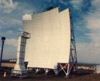
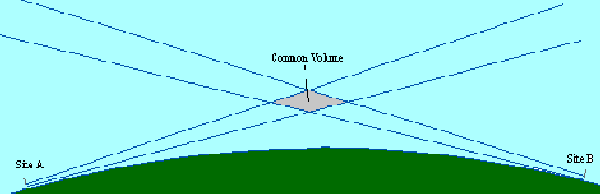
At each site, radio frequency (RF) energy from the transmitter was conducted to the feedhorn, via a waveguide, a form of transmission line designed for low loss. The feedhorn directed the energy towards the reflector. In the 64th Air Division case, the reflector was a concave "billboard" but the shape was only for practical reasons, the effect was the same as the "dish" type antennas seen on satellite systems. The reflector focused the RF energy into a fairly tight "beam" which was pointed at the "common volume". The common volume was the area of the troposphere, up to about six miles above earth, where the beams from both sites, which had spread to cover a much larger area, converged. Within the common volume, much of the RF energy passed through, into space, but enough of it is scattered back to earth to provide a useful signal strength at the distant site.
At the receiving site, the small amount of signal received from the transmitting site was directed by the reflector to the feedhorn, down the waveguide, through a filtering network and into the down-converter, where it was amplified and converted back to the IF frequency. It was then amplified again by the IF amplifier, before being converted, in the demodulator, back to the baseband frequency. Finally, it was routed to the multiplex to be broken up into individual circuits, again. The photos which we have on our web site for Hopedale have been examined by reputable sources. We have been advised that it appears that there were two pairs of Troposcatter antennae at Hopedale and these have been identified as the 60 foot billboard and the larger 120 foot billboard antennae. As a rule, a radar station such as the one in Hopedale would have had two pairs of Troposcatter antennae. There would have been a transmitter and a receiver antenna in each pair, and in Hopedale, we have been advised that one pair faced north towards Saglek, while the other pair faced west towards Goose Bay, thereby ensuring ongoing communications along the northeast.
-- Ren L'Ecuyer